
mcDSA-S65-LP
Articlenumber: 1504921


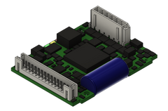
Motor controller up to 10 A
Compact four-quadrant controller for Stepper motors
CAN Interface (protocol DS301, Device profile DS402)
integrated digital inputs
integrated digital outputs
integrated analog inputs
Overvoltage, undervoltage and overtemperature monitoring
Device status notification with the help of 3 LEDs (Power, Status, Error)
Easily programmable due to built-in MPU (Motion Process Unit)
| Name | Value |
|---|---|
| 35 mA | |
| 9 .. 30 V | |
| 9 .. 60 V | |
| 3.5 A | |
| 3 A | |
| 10 A | |
| 85% Up | |
| 32 kHz | |
| symmetrical | |
| no | |
| no | |
| no | |
| yes | |
| Wall | |
| Crimp technology | |
| 53 x 41 x 13 mm | |
| 18 g | |
| no | |
| 2.0B | |
| 1 Mbit/s | |
| DS402 | |
| DS301 | |
| 0.2 A | |
| 5 V | |
| 0 .. 5 V | |
| 100 kHz | |
| A,B,Inx | |
| open collector, single ended | |
| incremental | |
| 8 .. 30 V | |
| 0 .. 5 V | |
| Din2 parallel with Dout0 | |
| 3 (Din0..2) | |
| 1.5 A | |
| resistive, inductive | |
| Dout0 parallel with Din2 | |
| 1 (Dout0) | |
| Electronic supply voltage Ue | |
| positive switching | |
| 1 (Ain0) | |
| +/- 10 V, 12 Bit, single ended |
1No reverse polarity protection, the destruction limit is at overvoltage of >= 33V or short-term peak voltage of 37V < 1s
2power amplifier switched off, 5V output (sensor supply) is free
3No reverse polarity protection, the destruction limit is at overvoltage of >= 80V
4connector cable with max. possible cable cross-section, PWM frequency 32 kHz, ambient temperature 40 °C (t >40 °C derating), RMS current: 3.5 A → 2.9 Aeff, 3 A → 2.4 Aeff
no guarantee, since value is determined empirical, please consider the application notes to determine the continuous current
no guarantee, since value is determined empirical, please consider the application notes to determine the continuous current
5connector cable with max. possible cable cross-section, PWM frequency 32 kHz, ambient temperature 40 °C (t >40 °C derating), RMS current: 3.3 A → 2.9 Aeff, 3 A → 2.4 Aeff
no guarantee, since value is determined empirical, please consider the application notes to determine the continuous current
no guarantee, since value is determined empirical, please consider the application notes to determine the continuous current
6default value